Structural Fastener – Line ASTM A325

Hex Structural Fasteners – Line ASTM A325 – TYPE 1

High resistance fasteners, used in structural screwed connections and indicated in the assembling of higher responsibility. Manufactured in high-resistance and thermally treated steel, the ASTM A325 bolts are also different from the common bolts as they have a higher hex head size, named “heavy”, and the thread length is smaller. Nuts are also compatible with the heavy hex wrench, according to the standard ASTM A194 Degree 2, and the washers follow the standard ASTM F436 Type 1.

Request a budget

Benefits

Reliability for the mechanical properties, standardized product
Products identified with standardized marking
Higher reliability compared to the welded junctions, as they have a known resistance
It does not require welding in many situations
Possibility of disassembling and reassembling

Applications

Conventional roofing structures (sheds, gantries, arches, fink, etc.)

Spatial roofing structures (mesh in tubular and laminated profiles)

Industrial and commercial sheds

Metallic structure buildings

Mezzanines and platforms

Pipe-rack.

Wheel track and overhead cranes

Runways and bridges

  • Commercial Data
  • Technical Data
  • How to Use
  • Downloads

HEAVY HEX NUT ASTM A194 GRADE 2H

DIAMETER THREAD (F.P.P) WRENCH PACKAGE (PIECE)
1/2” 13 UNC 7/8” 500
5/8” 11 UNC 1.1/16” 250
3/4” 10 UNC 1.1/4” 250
7/8” 9 UNC 1.7/16” 100
1” 8 UNC 1.5/8” 100


FLAT WASHER ASTM F436 TYPE 1

DIAMETER PACKAGE (PIECE)
1/2” 1000
5/8” 1000
3/4” 500
7/8” 500
1” 200


HEAVY HEX STRUCTURAL BOLT ASTM A325 TYPE 1

DIAMETER 1/2” 5/8” 3/4” 7/8” 1”
THREAD (F.P.P) 13 UNC 11 UNC 10 UNC 9 UNC 8 UNC
WRENCH 7/8” 1.1/16” 1.1/4” 1.7/16” 1.5/8”
MINIMUM
 THREAD LENGTH
1.1/4” 1.1/2” 1.1/2” 2” 2.1/4”
TOTAL
 LENGTH
TYPE OF
 THREAD
PACK. (Piece) TYPE OF
 THREAD
PACK. (Piece) TYPE OF
 THREAD
PACK. (Piece) TYPE OF
 THREAD
PACK. (Piece) TYPE OF
 THREAD
PACK. (Piece)
1.1/4” TOTAL 500* TOTAL 250* TOTAL 150*
1.1/2” PARTIAL 400* TOTAL 250* TOTAL 150*
1.3/4” PARTIAL 400* PARTIAL 250* PARTIAL 150* TOTAL 100*
2” PARTIAL 300* PARTIAL 200* PARTIAL 150* TOTAL 100* TOTAL 50
2.1/4” PARTIAL 300* PARTIAL 200* PARTIAL 100* PARTIAL 100* TOTAL 50
2.1/2” PARTIAL 300* PARTIAL 200* PARTIAL 100* PARTIAL 50* PARTIAL 50
2.3/4” PARTIAL 300* PARTIAL 150* PARTIAL 100* PARTIAL 50* PARTIAL 50
3” PARTIAL 250* PARTIAL 150* PARTIAL 100* PARTIAL 50* PARTIAL 50
3.1/4” PARTIAL 150* PARTIAL 100* PARTIAL 50* PARTIAL 50
3.1/2” PARTIAL 150* PARTIAL 100* PARTIAL 50* PARTIAL 50
3.3/4” PARTIAL 150* PARTIAL 100* PARTIAL 50* PARTIAL 50
4” PARTIAL 100* PARTIAL 50* PARTIAL 50* PARTIAL 50
4.1/4” PARTIAL 50* PARTIAL 50
4.1/2” PARTIAL 50* PARTIAL 25
4.3/4” PARTIAL 25
5” PARTIAL 25

*All the items are supplied with hot-galvanized coating, in the quantities informed in the tables as units.

COMPOSITION:

Material: Medium carbon steel with quenched tempering

FINISHING LAYER THICKNESS RESISTANCE TO CORROSION
SALT-SPRAY¹ KESTERNICH²
HOT GALVANIZED 50 MICRONS N/A³ N/A³
WHITE GALVANIZED 5 MICRONS 48 HOURS N/A³

1 – Standards ASTM B117, ABNT NBR 8094 and DIN 50021 (red corrosion).
2 – Standard DIN 50018 (allowing 15% of red corrosion in the bolt head).
3 – Test not applicable. Line ASTM A325 follows, as tightening parameter, the table 16 of standard ABNT NBR 8800.

According to the standard NBR 8800:2008, the bolts tightening control can be made by three processes:

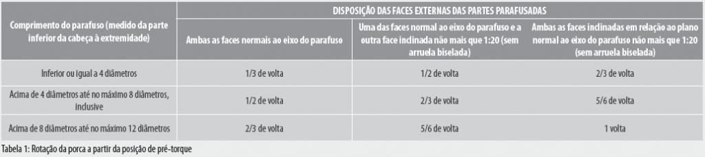
1 – Tightening by the nut revolution: In this method, to apply the minimum prestressing force specified in the Table 15 of standard NBR 8800:2008, there should be a sufficient number of bolts in the pre-torque condition, in order to assure that the parts are in full contact. The pre-torque condition is defined with the tightening obtained after few impacts applied with an impact wrench or by the maximum effort applied by a person using a common wrench. After this initial operation, bolts should be placed in the remaining holes, and also taken to the pre-torque condition. Then, all the bolts are applied with the additional tightening by means of the applicable bolt revolution, as indicated in the Table 1. Both the additional tightening and the final torque is started by the most rigid part of the connection and proceeding toward the free edges. During this operation, the portion opposite to the part that receives the rotation can not spin.

2 – Tightening with calibrated wrench or manual wrench with torque meter: There is no general relationship between the prestressing force in bolts and the torque applied during the nut tightening, due to several factors, including the friction conditions on the surfaces with relative movement. Torque tables based on past experiences or provided in technical literatures can be used.
These wrenches should be adjusted to provide a minimum prestressing 5% higher than the prestressing provided in the Table 15 of standard NBR 8800:2008 and reproduced in the ’’mechanical properties’’ folder. Wrenches should be calibrated at least once at a working day, for each bolt diameter to be installed, and should be recalibrated when significant changes are made in the equipment or when significant differences are observed in the conditions of each surface of the bolts, nuts, and washers. For the other conditions, see item 6.7.4.4.2 of standard NBR 8800:2008.

3 – Tightening using a direct traction indicator: Tightening bolts is allowed using a direct traction indicator, since it is demonstrated that the bolt was subjected to the minimum prestressing force by a direct measurement method established in the Table 15 of standard NBR 8800:2008 and reproduced in the “mechanical properties’’ folder.

Budget for companies

Do you want to buy with your CNPJ? Click the button below and talk to one of our experts.

REQUEST A BUDGET